Surface ECA
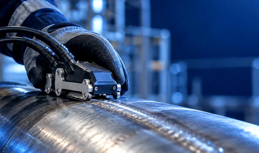
Components, weld-adjacent areas and other accessible surfaces.
Explore →ECA is a family of probe arrangements and inspection approaches, not a universal solution. The correct technique depends on conductivity, magnetic properties, surface condition, geometry, defect orientation and inspection standards.
Request a proposal Explore servicesInspection scope, suitable probe design, reference standards and reporting requirements should be determined for the actual asset. Where feasibility is uncertain, send the drawings and inspection objective for review.
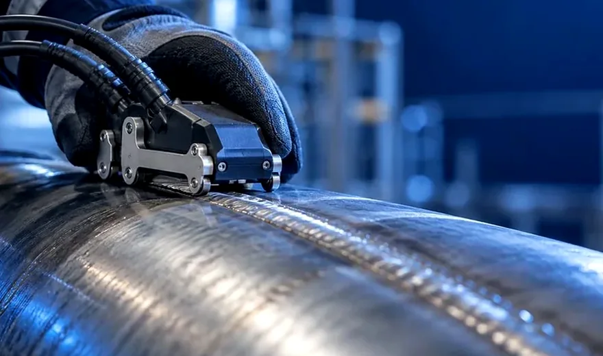
Evaluate weld and HAZ indications after reviewing profile, material and applicable criteria.
Explore application →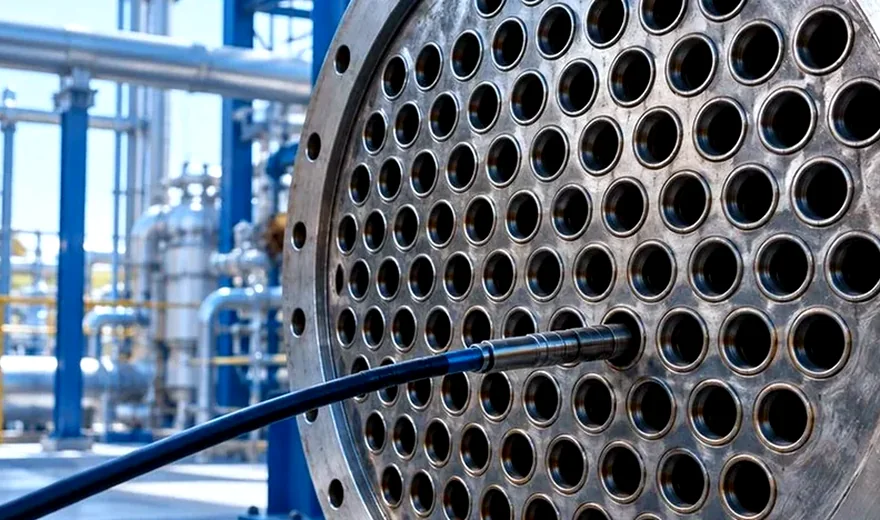
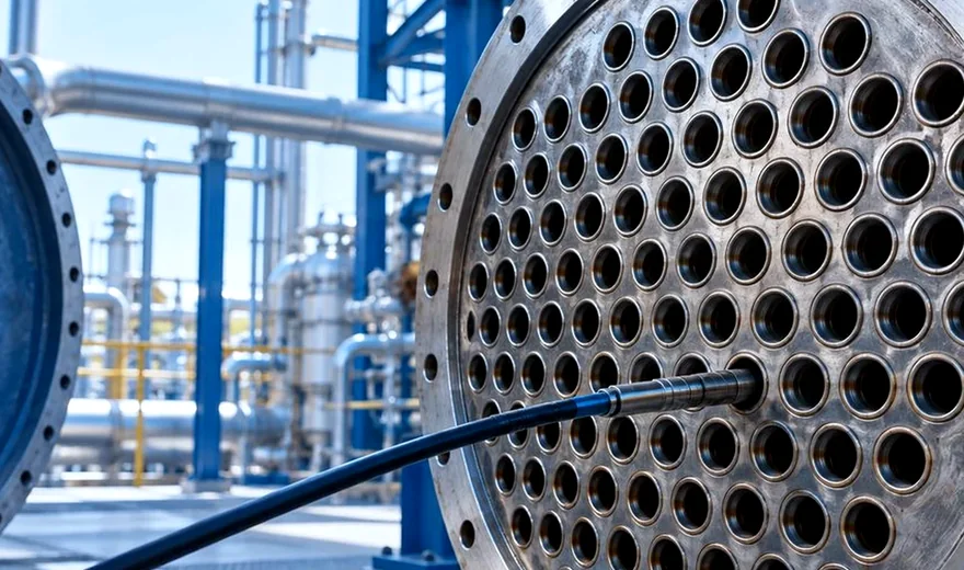
Evaluate localised and circumferential tube concerns with a compatible array probe.
Explore application →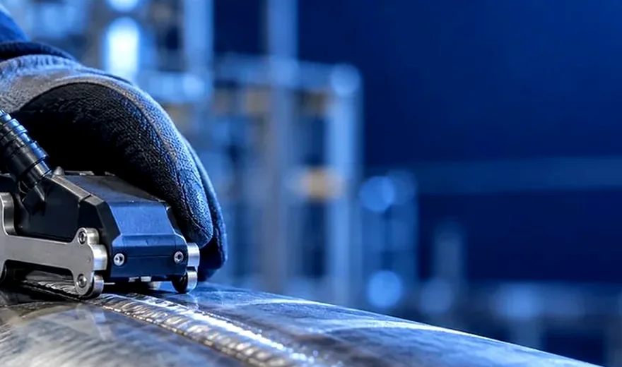
Evaluate accessible conductive structures and fatigue-prone details.
Explore application →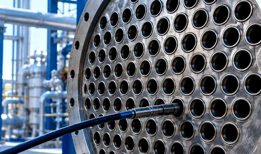
Review localised tube-end and support indications.
Explore application →Alternating current energizes probe coils. The changing magnetic field induces eddy currents in conductive material; discontinuities alter the measured response. An array places multiple coils across a probe footprint so signals can be assembled into a spatial view when scanning and encoding support it.
AC versus DC: Both conventional ECT and ECA use alternating excitation. A steady DC field alone does not provide the time-varying induction of standard eddy current flaw detection. The difference is the coil arrangement and acquisition.
| Method | Typical arrangement | Potential advantage | Key qualification |
|---|---|---|---|
| Single-coil surface ECT | One probe element scanned manually | Localised inspection | Raster coverage and position depend on the scan plan. |
| Surface ECA | Multiple elements in a shaped or flexible array | Broader swath and mapped data are possible | Coil pattern and geometry must suit the defect. |
| Tube bobbin ECT | Encircling coil pulled through a tube | Efficient general screening | Circumferential averaging can limit localised characterisation. |
| Rotating tube probe | Local coil rotates while advancing | Detailed local examination | Mechanical access and scan time matter. |
| Array tube probe | Multiple distributed channels | Circumferential information in compatible designs | Fit, alloy and target flaw govern performance. |
No technique is universally superior. Detection, sizing and speed are demonstrated for the actual scope.
The inspection route is selected for the actual material, geometry, access and damage objective. Standards are applied only when they are relevant to the agreed project procedure.
Method selection starts with material conductivity and magnetic properties, component geometry, surface condition, access, expected flaw orientation and the decision the inspection must support. Probe arrangement, frequency, reference standards, calibration, scanning pattern and reporting are then defined for the actual component.
Examples can include ASTM E3052-21 for examination of carbon steel welds using ECA, ISO 15549:2019 for general eddy current testing principles, and ISO 17643:2015 for eddy current testing of welds by complex-plane analysis. ASTM E243-24 addresses copper and copper-alloy tube ECT using encircling coils and is not an ECA-specific array procedure. The applicable edition, calibration approach and acceptance criteria should be agreed in the project procedure.
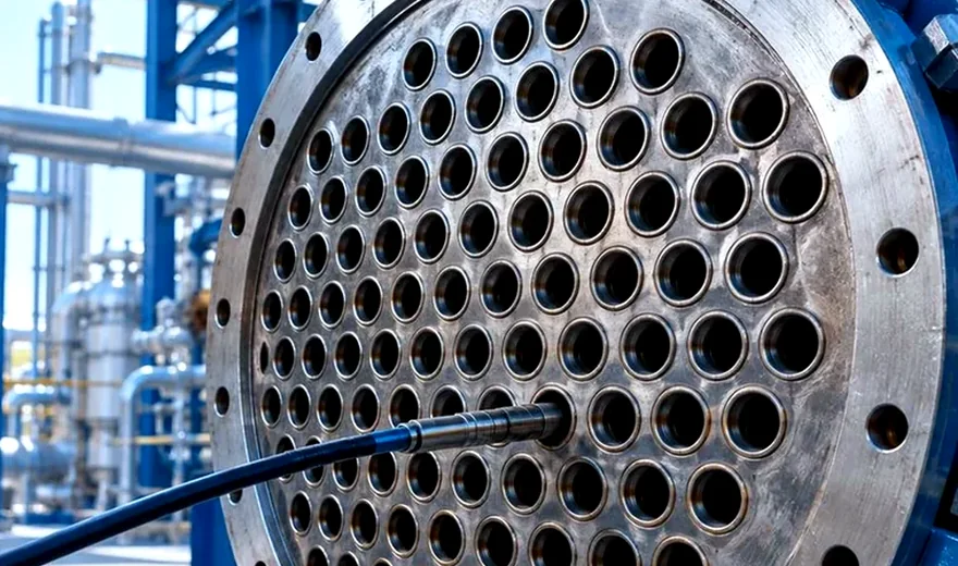
Refineries, petrochemical and chemical plants
View application →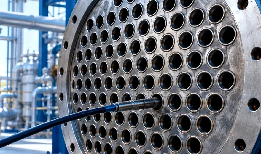
Power generation and process plant condensers
View application →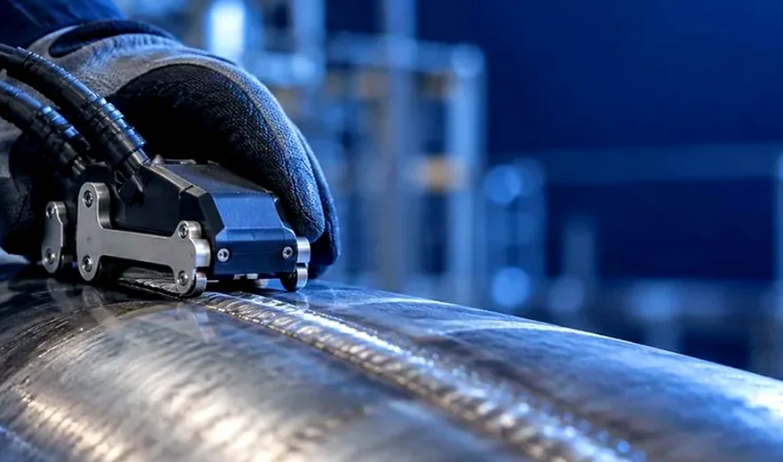
Oil and gas pipelines and process piping
View application →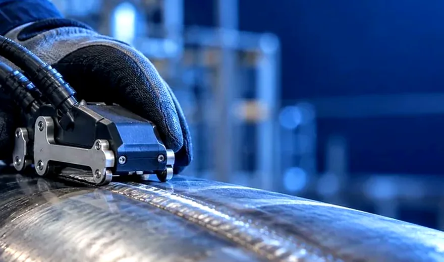
Pressure vessels, storage tanks and related welds
View application →Contact IAIS with the component details and required schedule. Inspection capability and commercial terms are confirmed after scope review.
Discuss your inspection