
Where it may fit
See indicative component and industry contexts.
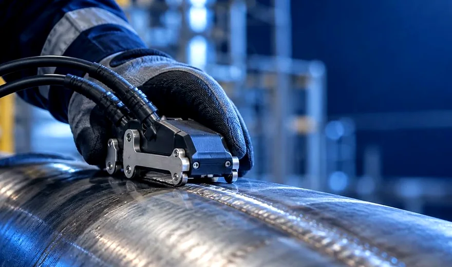
Explore →Surface ECA can help locate surface-breaking and certain near-surface indications in suitable electrically conductive components. Arrays can record encoded or position-related data across a probe footprint, depending on the instrument and scan arrangement. It is useful to discuss weld-adjacent regions, plate and structural surfaces, and complex geometries after confirming the appropriate probe.
Request a proposal Explore servicesInspection scope, suitable probe design, reference standards and reporting requirements should be determined for the actual asset. Where feasibility is uncertain, send the drawings and inspection objective for review.
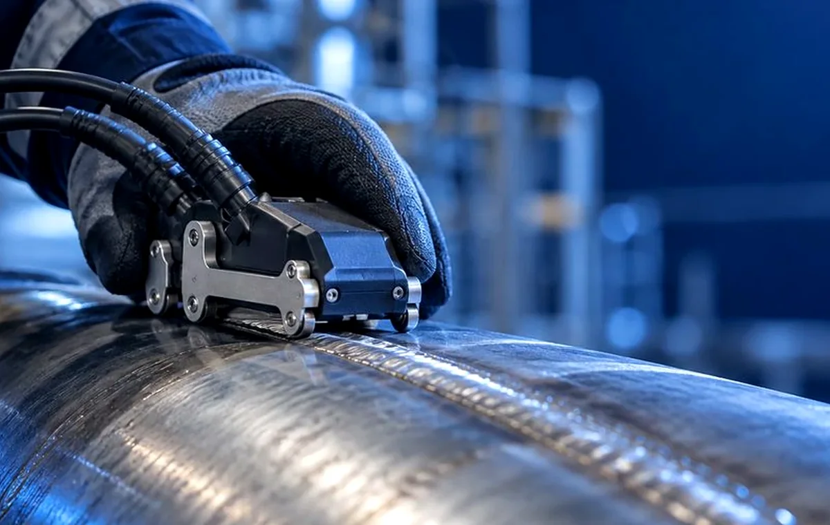
A surface ECA proposal starts with the likely defect and scan path. Carbon steel weld toes, plate surfaces and structural details require different probe geometry and calibration arrangements.
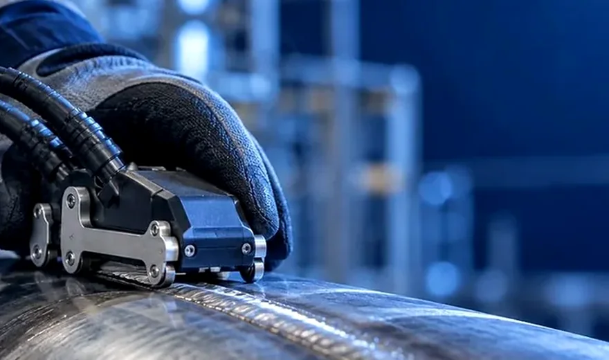
Review weld profile, cap condition, coating and surface-breaking flaw objective.
Explore application →
Review fatigue sites, access and feasible scan coverage.
Explore application →| Input | Why it matters |
|---|---|
| Material and magnetic properties | They influence frequency, signal response and probe selection. |
| Surface and coating | Roughness, lift-off and thickness can change sensitivity. |
| Weld geometry | Profile and toe access affect probe contact and coverage. |
| Defect objective | Orientation, depth and reference standard inform validation. |
The inspection route is selected for the actual material, geometry, access and damage objective. Standards are applied only when they are relevant to the agreed project procedure.
Method selection starts with material conductivity and magnetic properties, component geometry, surface condition, access, expected flaw orientation and the decision the inspection must support. Probe arrangement, frequency, reference standards, calibration, scanning pattern and reporting are then defined for the actual component.
Examples can include ASTM E3052-21 for examination of carbon steel welds using ECA, ISO 15549:2019 for general eddy current testing principles, and ISO 17643:2015 for eddy current testing of welds by complex-plane analysis. ASTM E243-24 addresses copper and copper-alloy tube ECT using encircling coils and is not an ECA-specific array procedure. The applicable edition, calibration approach and acceptance criteria should be agreed in the project procedure.
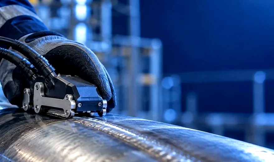
Oil and gas pipelines and process piping
View application →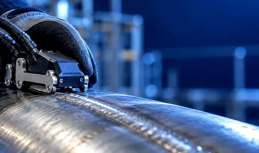
Pressure vessels, storage tanks and related welds
View application →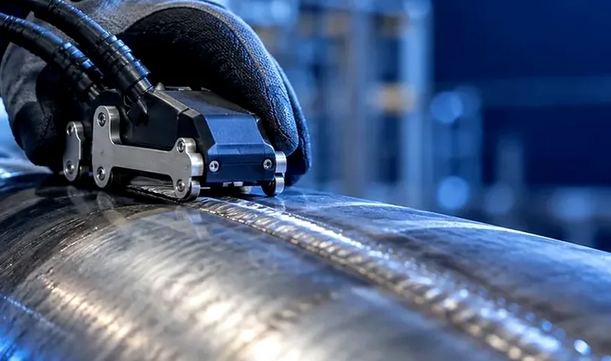
Power generation rotating equipment
View application →Compared with manually rastering a conventional single-coil surface probe, a suitable ECA probe can cover a wider path in each pass and provide more consistent spatial information. Encoded acquisition can make the coverage and indication position easier to review.
The benefit is application-specific: a small conventional probe can still be preferable for restricted geometry or targeted follow-up. Sensitivity and inspection speed depend on coil arrangement, surface condition, lift-off, scan plan and the reference standard. View the full method comparison →
Eddyfi explains that adjacent coils can be electronically multiplexed to limit coil interference and improve array resolution. Compared with a pencil probe raster scan, an appropriate array can cover a wider path in a simpler pass and produce data linked to position when encoded.
| Surface geometry or objective | Array approach described by Eddyfi | Planning consideration |
|---|---|---|
| Flat plate and accessible structural surface | Rigid or flexible ECA surface probe | Choose footprint, frequency and pass spacing for the target indication. |
| Curved piping and height variation | Semi-flexible or pipe-conforming array | Contact and lift-off change with curvature and coating. |
| Weld crown, toe and HAZ | Padded ECA or specialised tangential array (TECA) | Probe topology and calibration must suit weld profile and material. |
| Pipeline surface cracking | Specialised flexible ECA/TECA systems | Define crack orientation, coating, diameter and access. |
| Vessel or tank surface | Application-specific crack or corrosion array | Do not confuse surface crack assessment with volumetric UT or bulk wall-loss mapping. |
Source notes: Eddyfi ECA overview , semi-flexible probes , padded probes and TECA . Suitability remains component-specific.
Contact IAIS with the component details and required schedule. Inspection capability and commercial terms are confirmed after scope review.
Discuss your inspection