
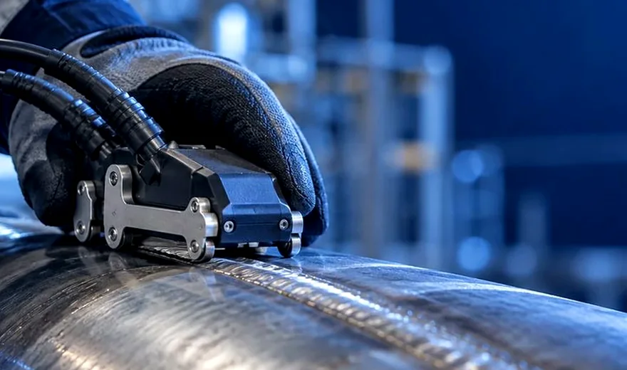
Surface inspection
Review surface-specific considerations.
Explore →A useful inspection proposal starts with the component drawing, material grade, thickness or tube dimensions, inspection objective, known damage mechanism, surface condition, access limitations, applicable code and reporting needs. The proposed technique, calibration reference, coverage and acceptance basis should be agreed for each scope. Company certifications or particular equipment models are provided only when verified for the proposal.
Request a proposal Explore servicesInspection scope, suitable probe design, reference standards and reporting requirements should be determined for the actual asset. Where feasibility is uncertain, send the drawings and inspection objective for review.
| Potential value | What must be checked |
|---|---|
| Coverage and repeatability | Probe footprint, pass spacing, access and encoded position control. |
| Reviewable data | Interpretation and verification remain necessary. |
| Preparation in some cases | Coating, roughness, weld profile and lift-off affect response. |
| Conductive materials | Conductivity and permeability influence probe choice. |
| Defect targeting | Flaw orientation, depth and reference reflectors must fit the procedure. |
The inspection route is selected for the actual material, geometry, access and damage objective. Standards are applied only when they are relevant to the agreed project procedure.
Method selection starts with material conductivity and magnetic properties, component geometry, surface condition, access, expected flaw orientation and the decision the inspection must support. Probe arrangement, frequency, reference standards, calibration, scanning pattern and reporting are then defined for the actual component.
Examples can include ASTM E3052-21 for examination of carbon steel welds using ECA, ISO 15549:2019 for general eddy current testing principles, and ISO 17643:2015 for eddy current testing of welds by complex-plane analysis. ASTM E243-24 addresses copper and copper-alloy tube ECT using encircling coils and is not an ECA-specific array procedure. The applicable edition, calibration approach and acceptance criteria should be agreed in the project procedure.
Eddyfi lists faster scanning, wider coverage, simpler scan patterns, more consistent results and improved encoded positioning as potential ECA advantages over a single-coil manual raster scan. These are technology-level comparisons. Actual inspection speed and flaw sensitivity depend on coil design, material, geometry, surface condition, probe fit, reference standards and operator qualification.
Specific Eddyfi DefHi tube and NFA air-cooler specifications describe those products only. This IAIS site does not claim those models, their numerical performance or a particular project qualification. Read Eddyfi’s ECA technology overview →
Contact IAIS with the component details and required schedule. Inspection capability and commercial terms are confirmed after scope review.
Discuss your inspection